Mixed Series and Parallel Circuits
Q1. In a circuit, resistors of 2 ohms and 4 ohms are connected in parallel across a cell supplying a potential difference of 6 volts. Another resistor of 5 ohms is connected in series with the cell.
(a) Draw the circuit.
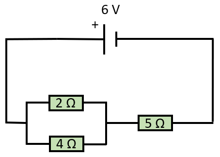
(b) Calculate the total resistance in the circuit.
This part of the question will involve calculating the overall resistance of two resistors in parallel. As we know, resistors in series are simply added up, so for example a 3 ohm resistor and a 5 ohm resistor in series would give a total resistance of 8 ohms, but how do we calculate the total resistance of the resistors in parallel?

We take the reciprocal of each resistance value, add them up and then take the reciprocal of the result, so in this particular case 1/2 + 1/4 = 3/4 and the Rt is therefore 4/3 Ω
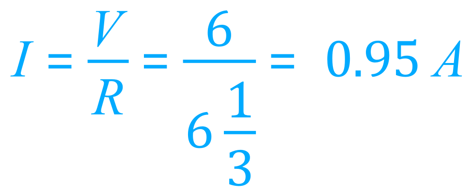
(c) Calculate the current flowing through the 5 ohm resistor.
Having evaluated the combined resistance of the resistors in parallel as 4/3 of 1 ohm, we can add to this 5 ohms to calculate the total resistance in the circuit. Since we know that the potential difference is 6 V and that the total resistance in the circuit is now 6 1/3 ohm we can evaluate the current across the 5 ohm resistor:
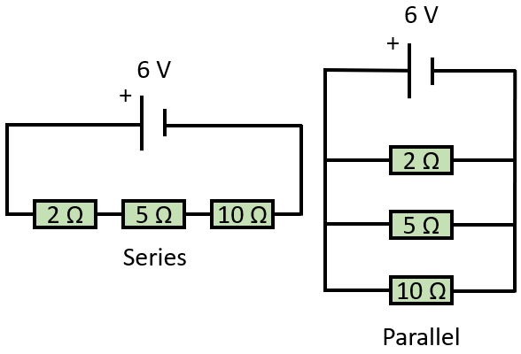
Q2. This question involves calculating the resistance of resistors in series and in parallel.Given three resistors of resistance 2 ohms, 5 ohms and 10 ohms respectively....
(a) Draw a circuit showing the resistors (a) in series and (b) in parallel.
(b) Calculate the total resistance of the circuit where the resistors are in series.
When the resistors are in series, the total resistance is this sum of the individual resistances, so in this case 2+5+10 = 17 ohms
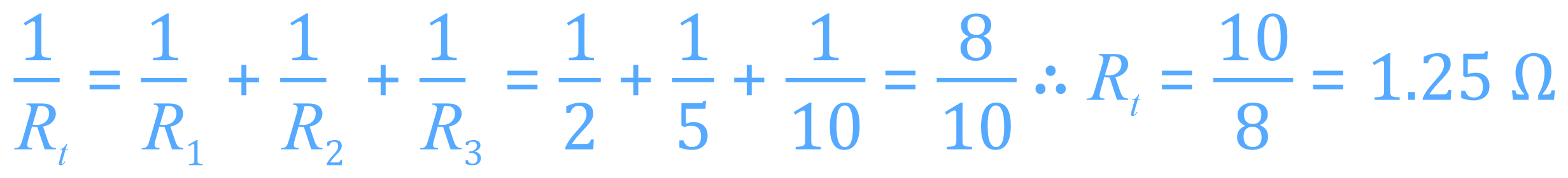
(c) Calculate the total resistance of the circuit where the resistors are in parallel.
When the resistors are in parallel, remember to take the reciprocal of each, add them up and then take the reciprocal of the answer:
(d) In which arrangement will the current in the circuit be larger? Explain your answer.
The current is inversely proportional to the resistance, as given by V = IR, so if the resistance increases with the potential difference remaining the same, the current must decrease.
In the series circuit V = IR so 6 = I x 17 giving a result of I = 6/17 = 0.35 A
In the parallel circuit V = IR so 6 = I x 1.25 giving a result of I = 6/1.25 = 4 A
So the current will be higher in the parallel circuit.
Q3. A parallel circuit is constructed as shown. When the switch is closed the ammeter A reads 0.75A
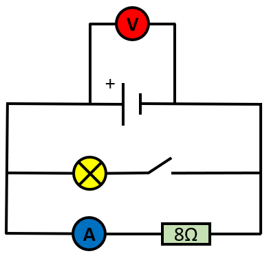
(a) Calculate the potential difference shown by voltmeter V
With the switch open, we end up with a simple series circuit containing an 8 ohm resistor and an ammeter. With the switch closed we have a parallel circuit containing a filament lamp and the 8 ohm resistor. We are told that when the switch is closed the ammeter read 0.75A, the potential difference across the branch containing the resistor would therefore be given by V = IR with values are 0.75 and 8 respectively for the current and resistance. The potential difference shown across V would therefore be 0.75×8 = 6V
(b) The total current in the circuit is 2.0A, calculate the resistance of the filament lamp.
We are given the total current in the circuit of 2 A. We know that in a parallel circuit the current splits across branches. Given the fact that the current passing through the 8 ohm resistor branch has already been given as 0.75 A we conclude that the current flowing through the filament lamp would be 2.0 - 0.75 = 1.25A. We know the potential difference to be 6V so the resistance of the filament lamp is R = V/I = 6/1.25 = 4.8Ω
(c) Is the total resistance of the circuit more than, or less than, or equal to, the answer you gave in (b) ?
The resistance of the circuit in total would be less than 4.8 ohm because we are told that the total resistance in a parallel circuit is always less than the value of the lowest resistance, one of the fundamental rules of parallel circuits. We can in fact calculate this value using the "reciprocal resistance" equation shown previously:
1/Rt = 1/R1 + 1/R2 = 1/4.8 + 1/8 = 0.3333......
The value for Rt would therefore be the reciprocal of 0.3333...... which is 3 ohms.
Q4. Study the circuit diagram shown below:
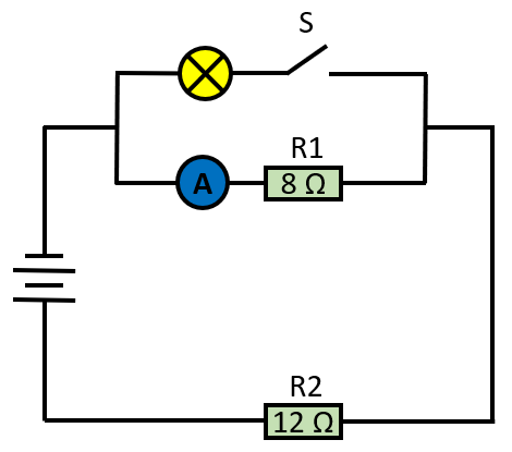
(a) If the switch "S" is open, ammeter A read 0.70 A. Find the potential difference across the battery.
You should be able to see that with switch "S" open, we have a simple series circuit with 2 resistors in series of 8 ohms and 12 ohms respectively. We are also told that in this situation the current reading on ammeter A is 0.70 A. From V = IR we can work out that the potential difference across the battery/cell would be 0.7 x (8+12) = 14 V
(b) If the switch "S" is closed, ammeter A reads 0.50 A.
(i) Find the potential difference across lamp B
When the switch "S" is closed, the reading on ammeter A is 0.50 A. The potential difference across resistor R1 is therefore 4 V from V = IR using a value for I of 0.5 and a value R of 8. This part of the circuit is parallel, and we know that the potential difference across branches of a parallel circuit is the same in each branch, Therefore if the potential difference across the 8 ohm resistor is 4V then it must be the same potential difference across the filament lamp, 4V.
(ii) Find the potential difference across resistor R2
Although the top half of the circuit in itself is a parallel circuit, taken along with the part of the circuit containing resistor number 2, we have a series circuit overall. In a series circuit we know that the potential difference is shared across all components and we have now worked out that the potential difference across the filament lamp/resistor R1 is 4V.
The total potential difference is 14V so the potential difference across resistor R2 is 14-4 = 10V.
If you're not sure about how these values were arrived at, return to the summary and study the equations.
Back to >> Questions <<
Back to >> Parallel Circuits <<