Potential Difference in Series Circuits
The potential difference is the "driving force" in the circuit, so you will understand that if you increase the potential difference you increase the strength of this "driving force". In series circuits the total potential difference available is shared across all of the components in the circuit, so if for example we have a potential difference of 12 V and there is only one component in the circuit (for example a 12 V rated lamp) then there will be a potential difference of 12 V across the lamp. If we add another lamp of the same rating as the first one, the potential difference will be shared between the two and will show as 6 V across each lamp. Of course certain characteristics of the component will determine how much of the potential difference it receives, but the total potential difference across all components will add up to the source potential difference:
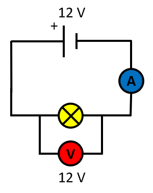
As was mentioned above, in this situation (shown in the circuit diagram above) the potential difference across the filament bulb will show on the voltmeter as 12 V (provided that the bulb can take this amount of voltage otherwise it may simply blow out).
In the following diagram, the situation is slightly different:
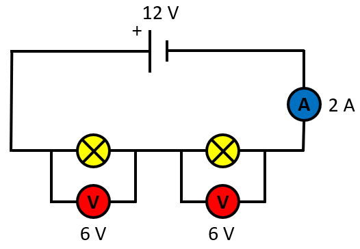
Now we have two identical bulbs sharing the 12 V potential difference coming from the source cell, as the potential difference is shared across each component in the series circuit we would observe that each of the volt meters would read 6 V.
If we call the potential difference reading of the first voltmeter V1 and that of the second voltmeter V2 we can then state:
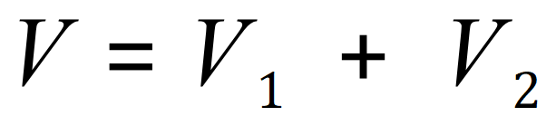
As indeed...12 = 6 + 6.
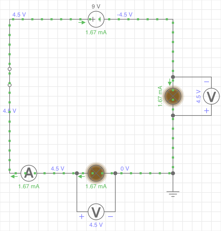
The above image is taken from a circuit simulator. The Potential Difference is 9 V which is shared across two identical filament lamps, so as expected the PD across each is 4.5 V. As we shall see in the next section, the current (in this case 1.67 mA) is the same throughout the circuit. This is a feature of series circuits.